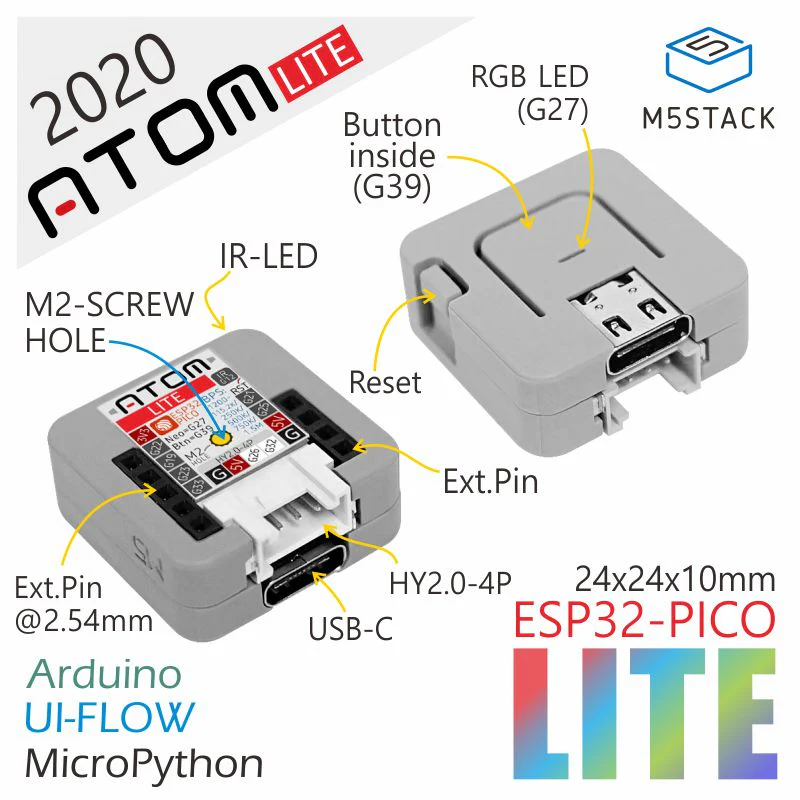
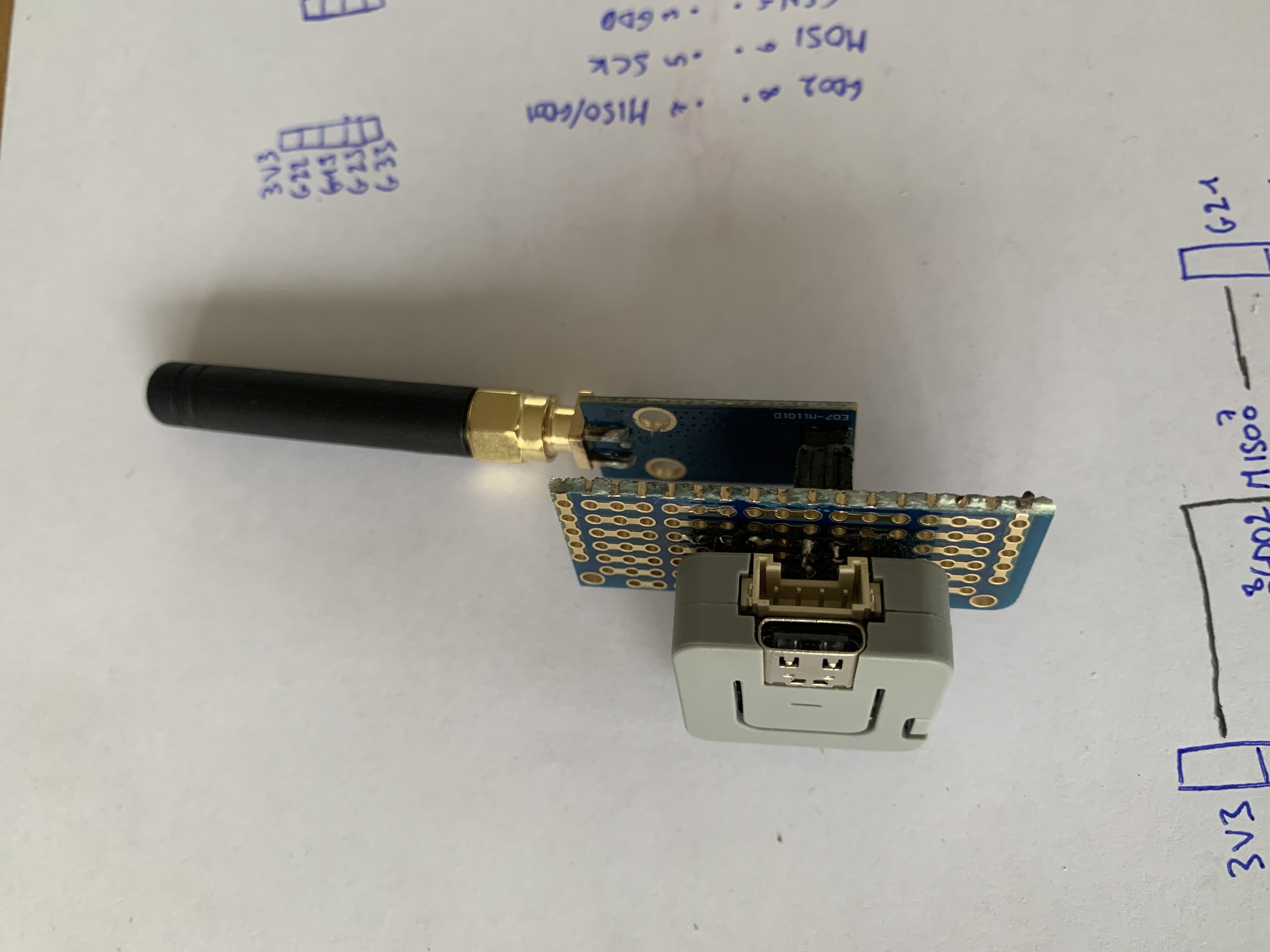
I have an Atom Lite and wanted to use it to install ESPSomfy-rts on it with a E07-M1101D antenna.
The goal is to control Somfy covers with Home Assistant.
If you have the same setup, you might enjoy some opinionated instructions. So these are the steps I followed.
Installation
These are the steps are followed to flash my Atom Lite.
1. Plug the Atom Lite in the computer
With a USB cable!
2. Find the Atom Lite
If you have multiple ttyUSB devices,
repeat the command after disconnecting the Atom Lite and see which one disappeared.
$ ls -l /dev/ttyUSB*
crw-rw---- 1 root dialout 188, 0 Jun  4 12:02 /dev/ttyUSB0
3. Enter shell with needed tools
Yay for nix!
nix-shell -p unzip curl esptool4. Check Atom Lite is flashable
For good measure but I suppose you could skip this step.
$ sudo esptool --port /dev/ttyUSB0 flash-id
esptool v5.2.0
Connected to ESP32 on /dev/ttyUSB0:
Chip type:          ESP32-PICO-D4 (revision v1.1)
Features:           Wi-Fi, BT, Dual Core + LP Core, 240MHz, Embedded Flash, Vref calibration in eFuse, Coding Scheme None ta
Crystal frequency:  40MHz
MAC:                64:b7:08:b7:98:08

Stub flasher running.

Flash Memory Information:
=========================
Manufacturer: c8
Device: 4016
Detected flash size: 4MB
Flash voltage set by a strapping pin: 3.3V

Hard resetting via RTS pin...
5. Erase the Atom Lite
I’m not sure this is needed but it won’t hurt.
$ sudo esptool --port /dev/ttyUSB0 erase-flash6. Download the firmware
From the release page, download the *.onboard.esp32.bin.zip archive
or copy paste the curl command and update the release version:
$ curl -LO https://github.com/rstrouse/ESPSomfy-RTS/releases/download/v2.4.7/SomfyController.onboard.esp32.bin.zip
$ unzip SomfyController.onboard.esp32.bin.zip
Archive:  SomfyController.onboard.esp32.bin.zip
  inflating: SomfyController.onboard.esp32.bin
7. Flash the Atom Lite
This step took about a minute for me.
$ sudo esptool --port /dev/ttyUSB0 \
    write-flash 0x0 SomfyController.onboard.esp32.bin
esptool v5.2.0
Connected to ESP32 on /dev/ttyUSB0:
Chip type:          ESP32-PICO-D4 (revision v1.1)
Features:           Wi-Fi, BT, Dual Core + LP Core, 240MHz, Embedded Flash, Vref calibration in eFuse, Coding Scheme None
Crystal frequency:  40MHz
MAC:                64:b7:08:b7:98:08

Stub flasher running.

Configuring flash size...
Flash will be erased from 0x00000000 to 0x003effff...
Wrote 4128768 bytes (929394 compressed) at 0x00000000 in 91.0 seconds (363.1 kbit/s).
Hash of data verified.

Hard resetting via RTS pin...
8. Verify Installation
Now, the Atom Lite will create its own WiFi access point with name ESPSomfyRTS.
Hardware
1. Connect to Atom Lite’s WiFi AP
Connect to the ESPSomfyRTS network.
2. Load ESPSomfyRTS web interface
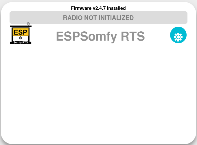
Go to http://192.168.4.1. The IP address is hardcoded. The webpage should show “RADIO NOT INITIALIZED”.
3. Configure device
Click on the gear icon. Go through the all the tabs first, we’ll configure the radio afterwards.
Don’t forget to click “save” before switching tab otherwise your changes will be lost.
You know what? Click twice on “save”, for good measure.
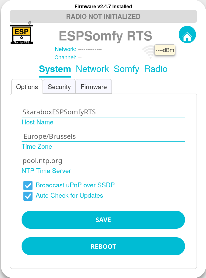
System > Options
System > Security
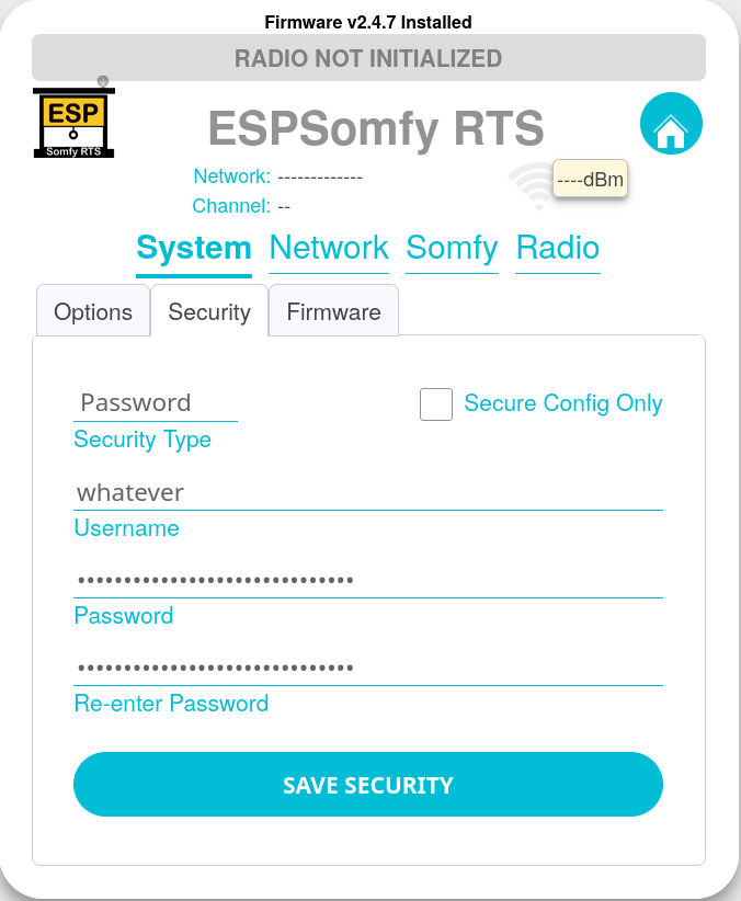
I store the username and password in Bitwarden (using my Vaultwarden self-hosted server).
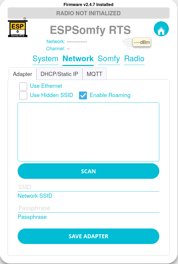
Network > Adapter
You don’t need to setup WiFi, you could always connect to the device through its ESPSomfyRTF WiFi AP
but then you’ll lose on the Home Assistant integration.
So I recommend doing it.
Somfy
Skip the Somfy tab for now, we need to setup the radio first.
4. Wiring
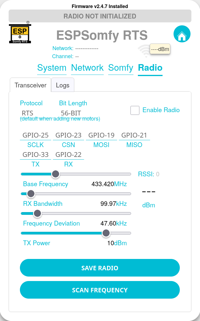
Radio > Transceiver
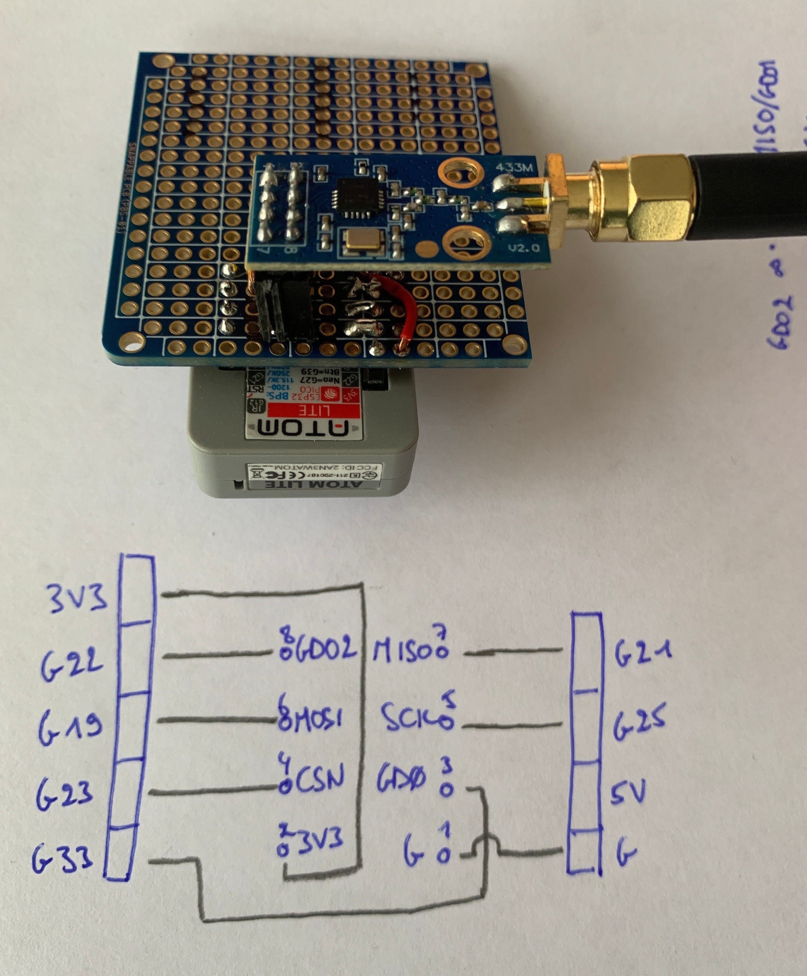
We will now configure the pinout with the following wiring. I chose this wiring specifically to make the physical wiring as simple as possible, considering the antenna would be located underneath the Atom Lite, with a breadboard in between.
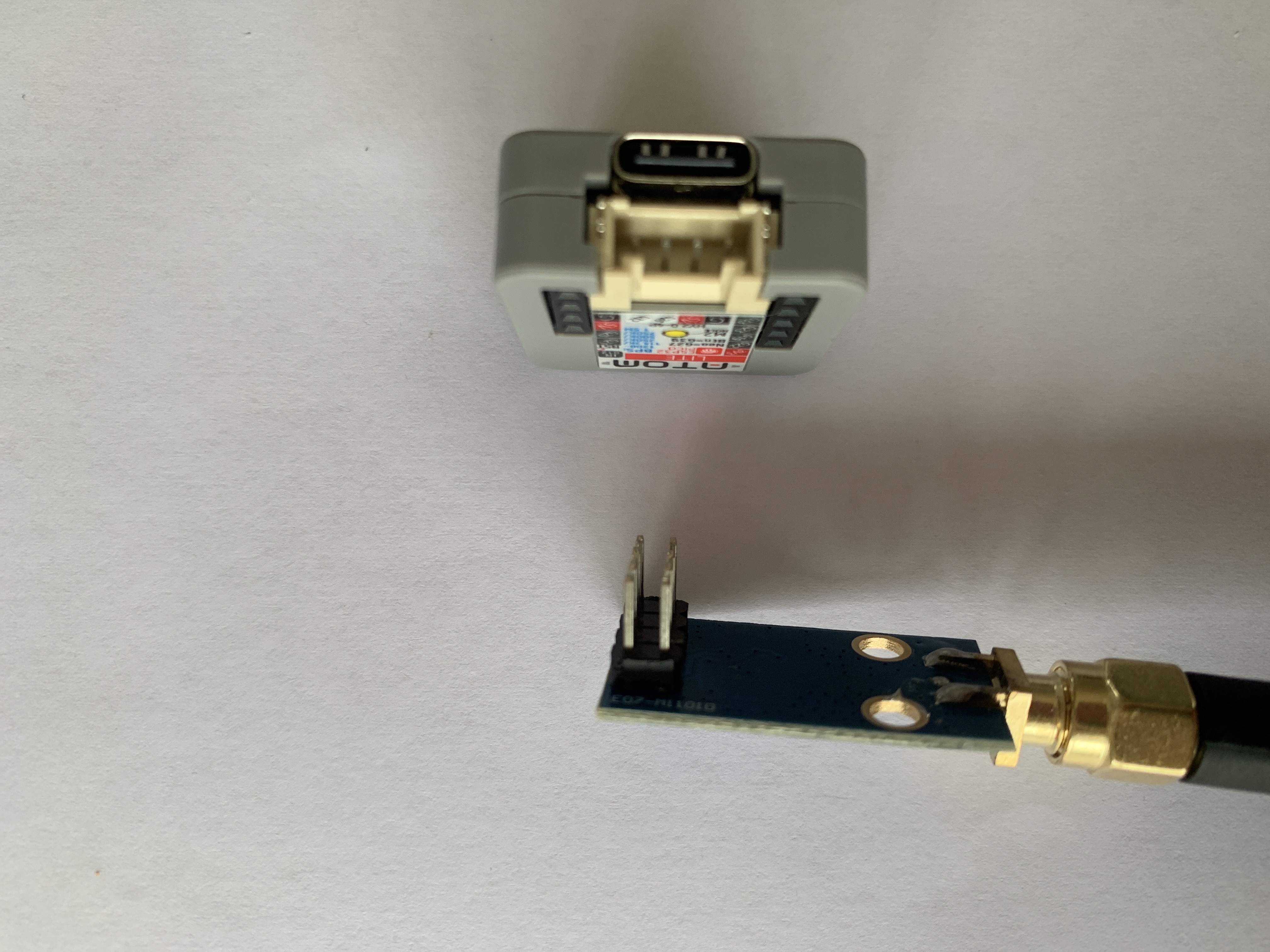
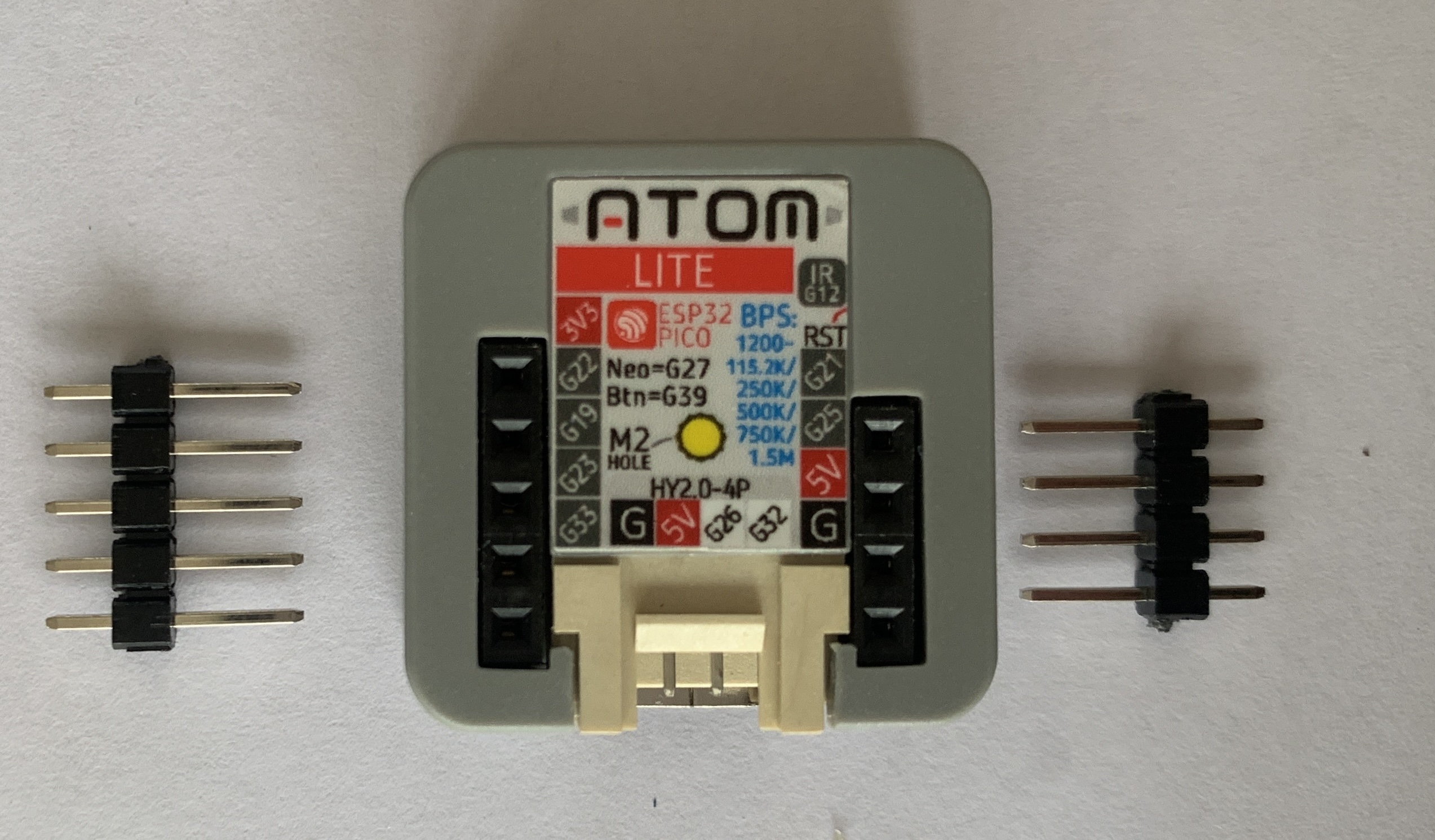
The pinout is shown here:
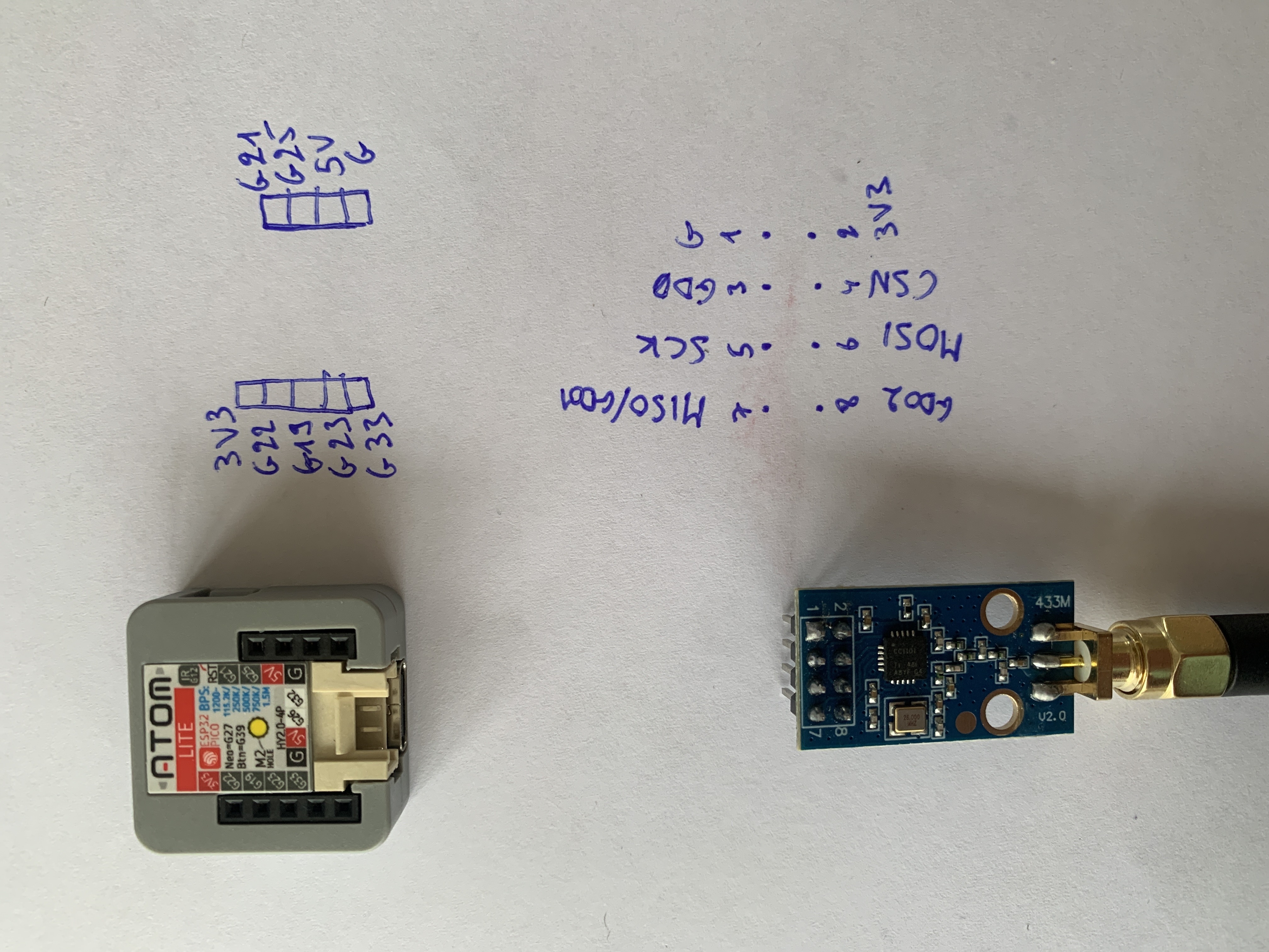
Combining both diagrams, we can see a quite neat wiring:
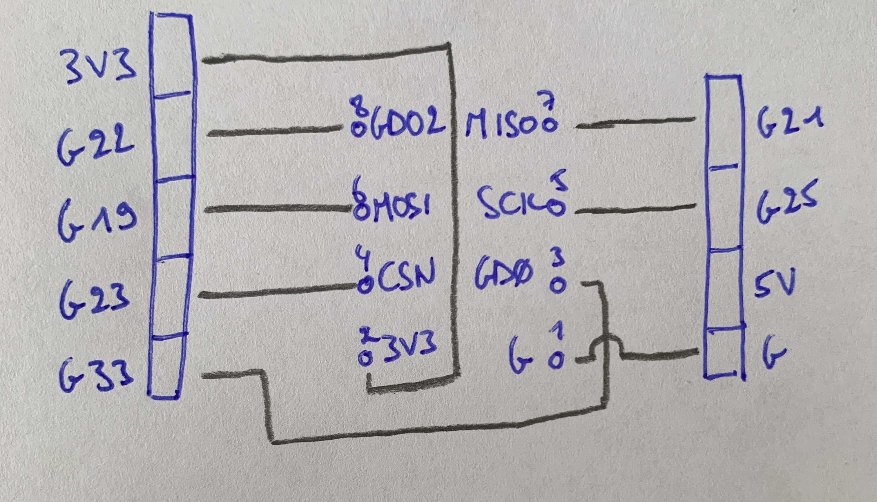
The correspondance is:
| Antenna | Atom Lite | ESPSomfyRTS |
|---|---|---|
| (1) Ground | Ground | - |
| (2) 3V3 | 3V3 | - |
| (3) GD0 | GPIO 33 | TX |
| (4) CSN | GPIO 23 | CSN |
| (5) SCK | GPIO 25 | SCLK |
| (6) MOSI | GPIO 19 | MOSI |
| (7) MISO | GPIO 21 | MISO |
| (8) GDO2 | GPIO 22 | RX |
Now, we can set the pinout correspondance in the web UI:
5. Test
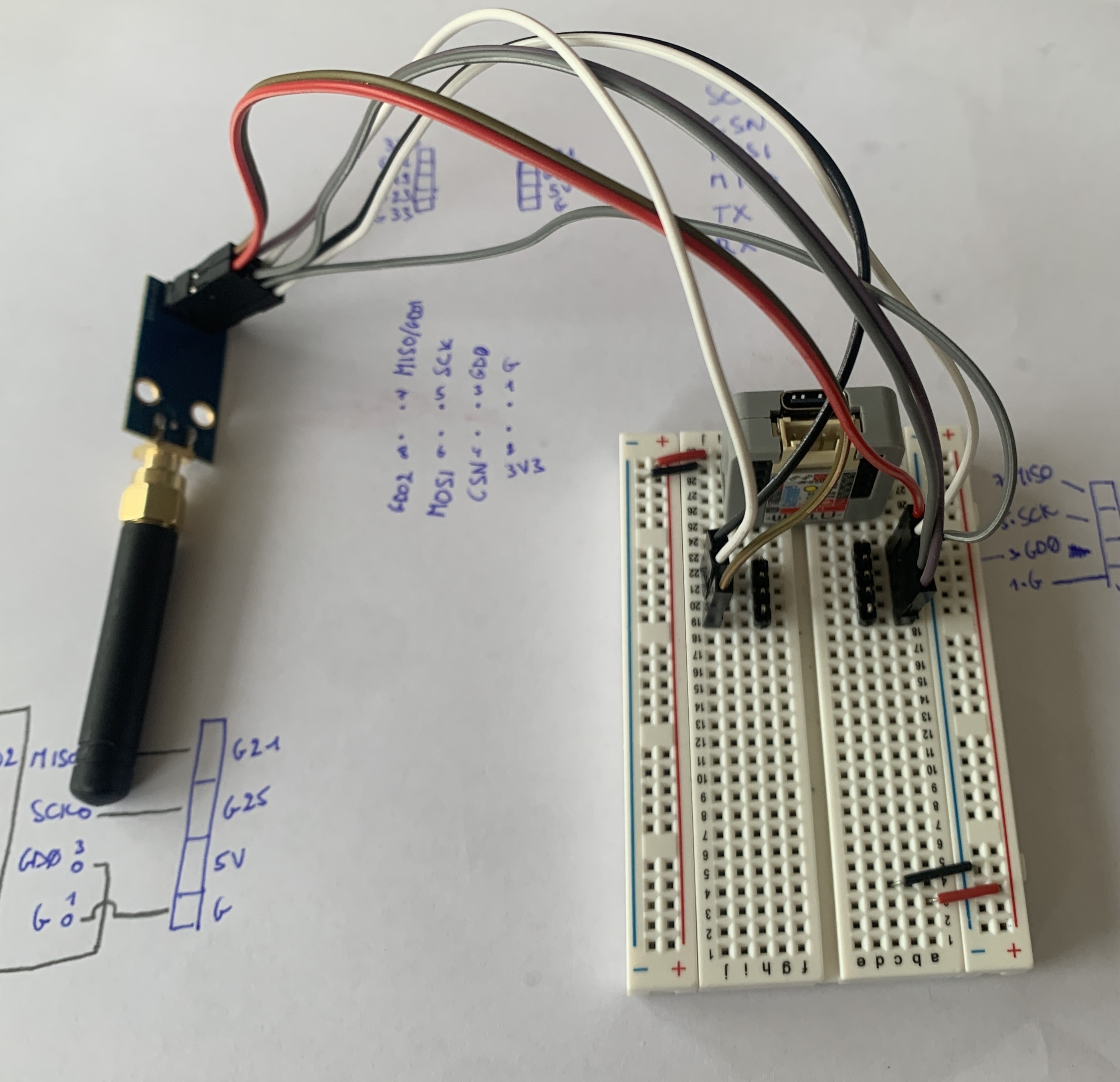
I’ll do first a test using a solderless breadboard. I’m using the male and female socket headers I’ll use later when soldering.
The breadboard setup looks like so. I had a hard time wrapping my head around where to put the wires because I needed to mirror the diagram from above.
Now, let’s enable the radio in the Radio > Transceiver tab in the web interface
by toggling the “Enable Radio” checkbox.
Then, click save.
To see if everything works fine, go to the Radio > Logs tab and press on the official Somfy remote,
you should see some log lines like so:
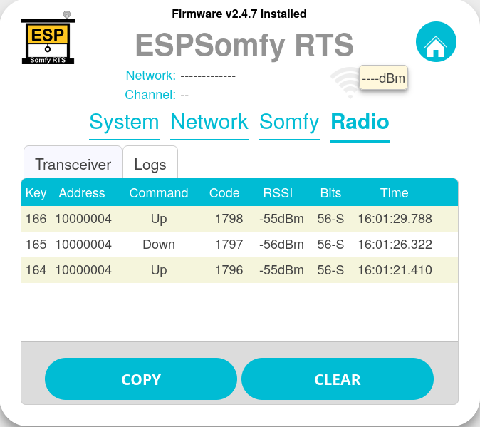
You could also configure already the rooms and covers but I’ll leave that for after the soldering.
6. Soldering
Since everything went well, it’s time to solder.
Comparing the breadboard used for soldering to the diagram,
you’ll see there’s an extra connection that we need to get rid of
between the GD0 pin from the antenna and the 5V pin from the Atom Lite.
I marked it in red.
Note the diagram is mirrored at the pink line.
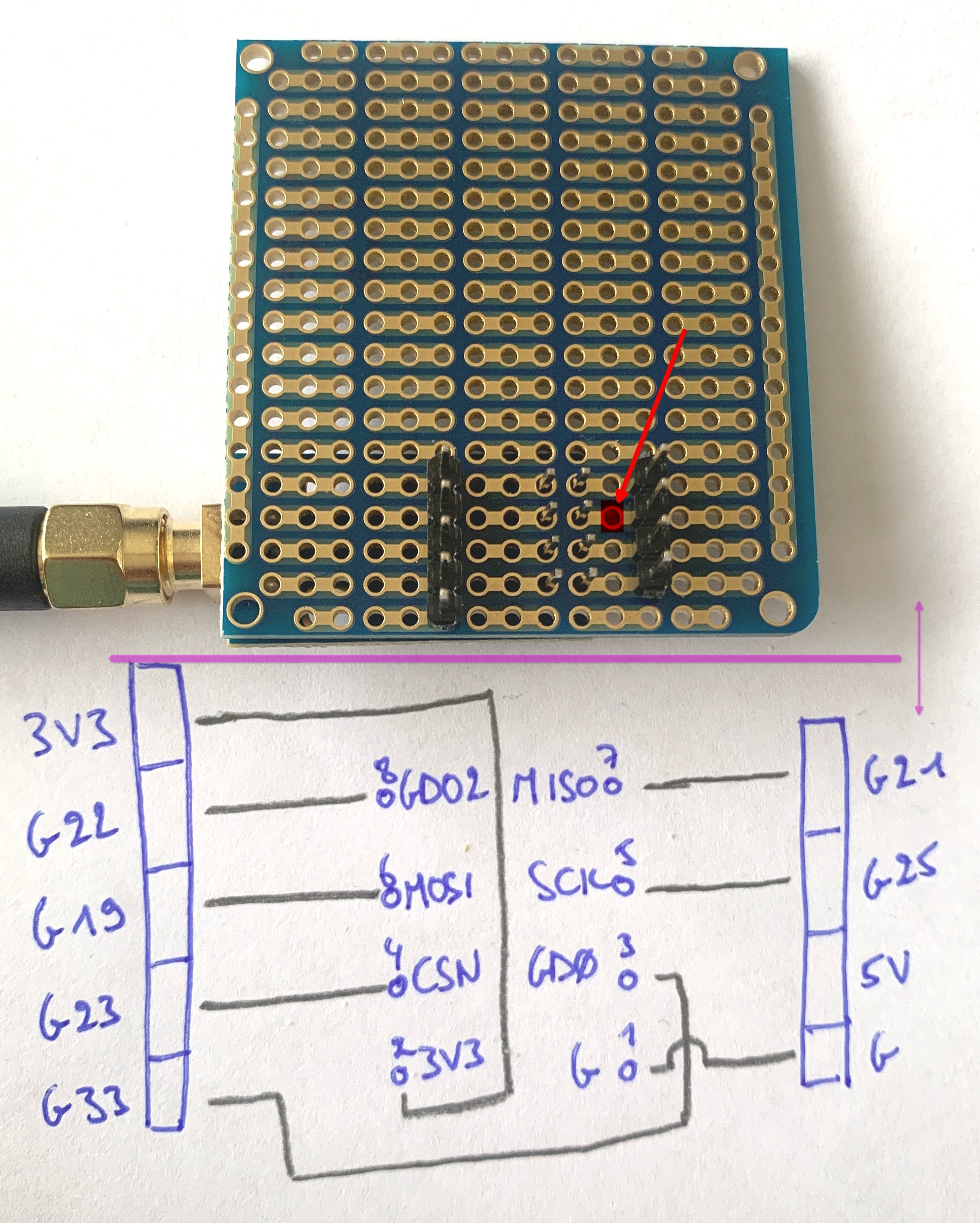
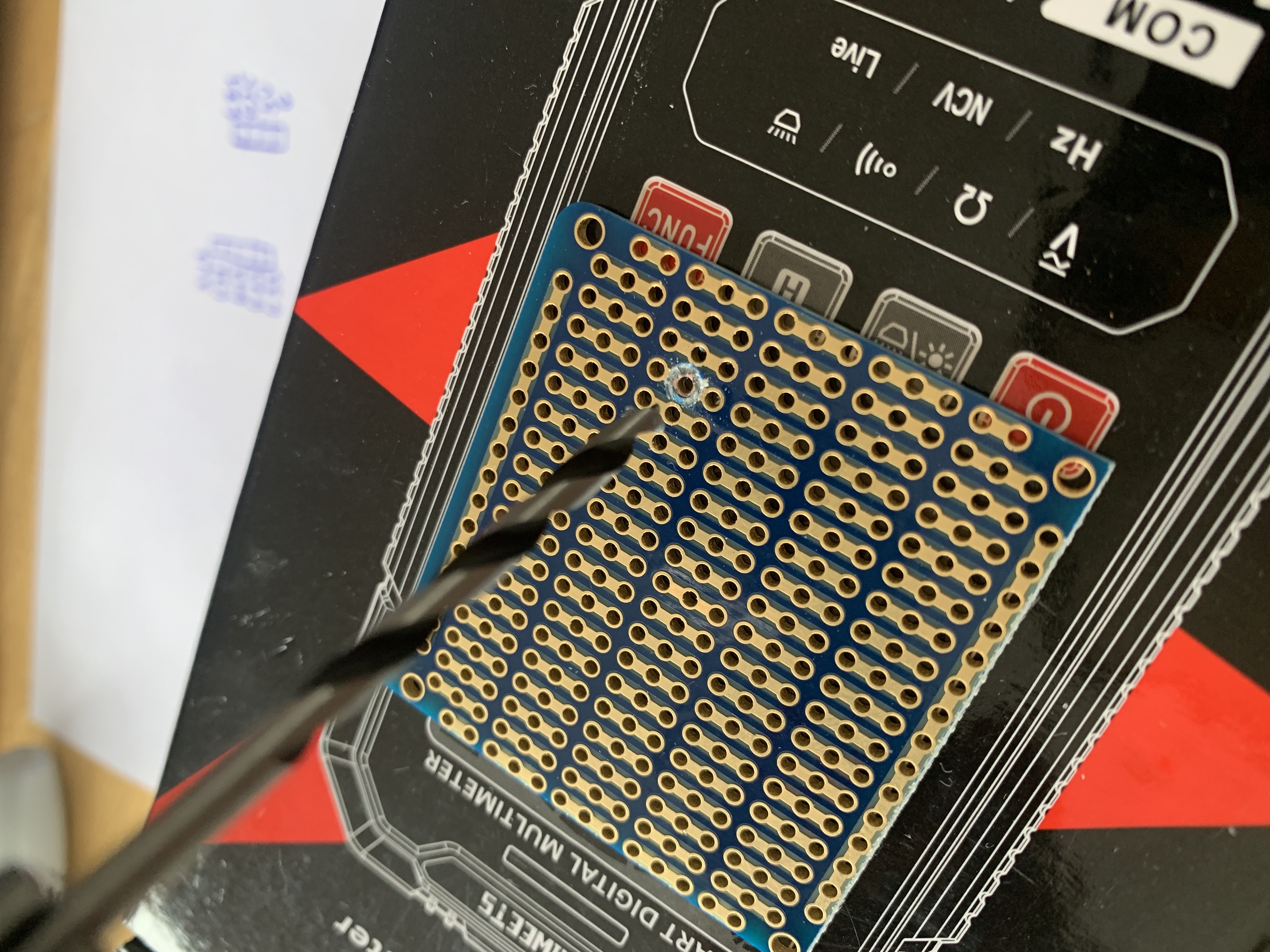
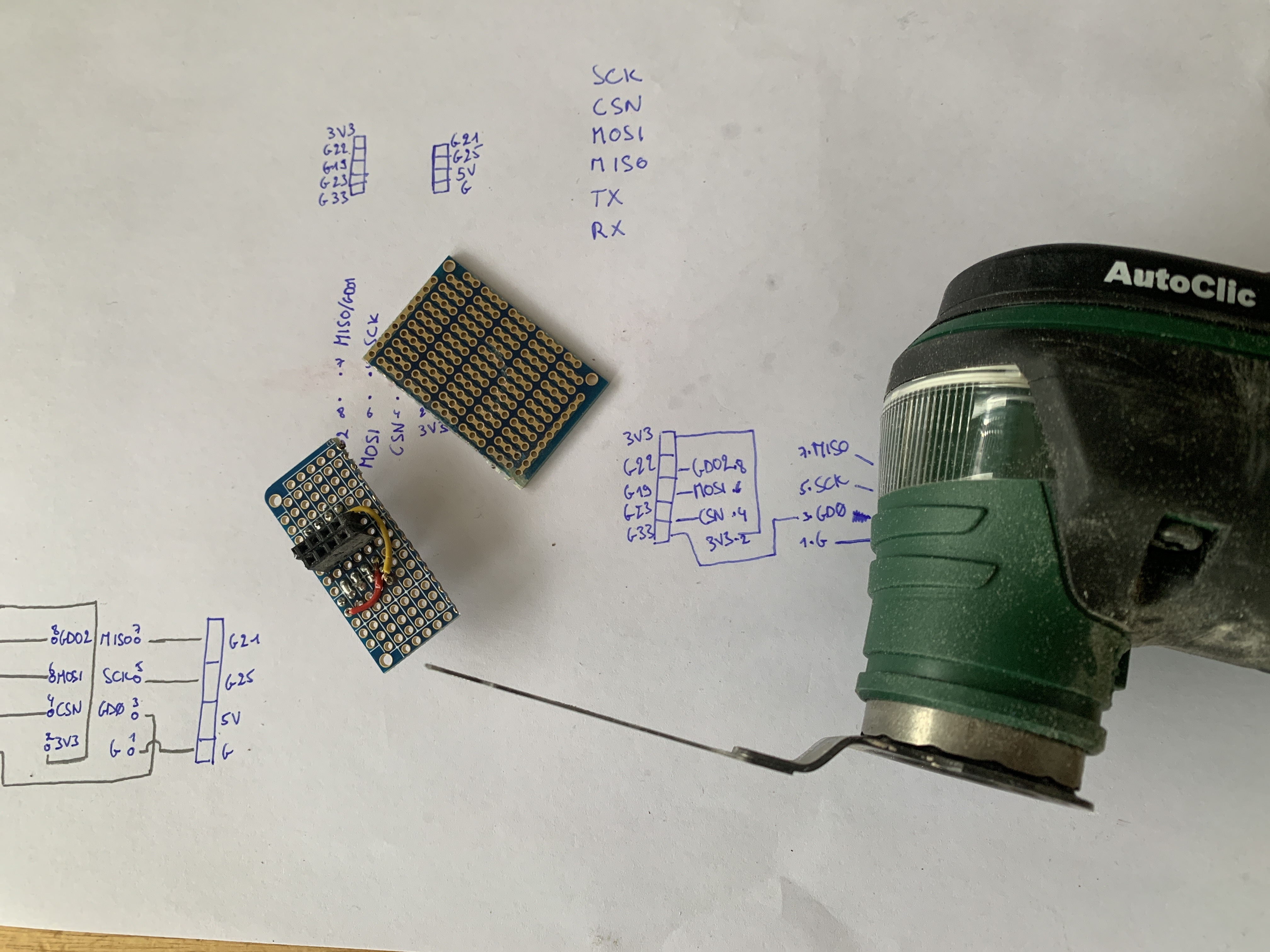
I used a drill with the smallest wood drill bit I had to cut the connection.
And a dremel to cut the female header sockets for the antenna.
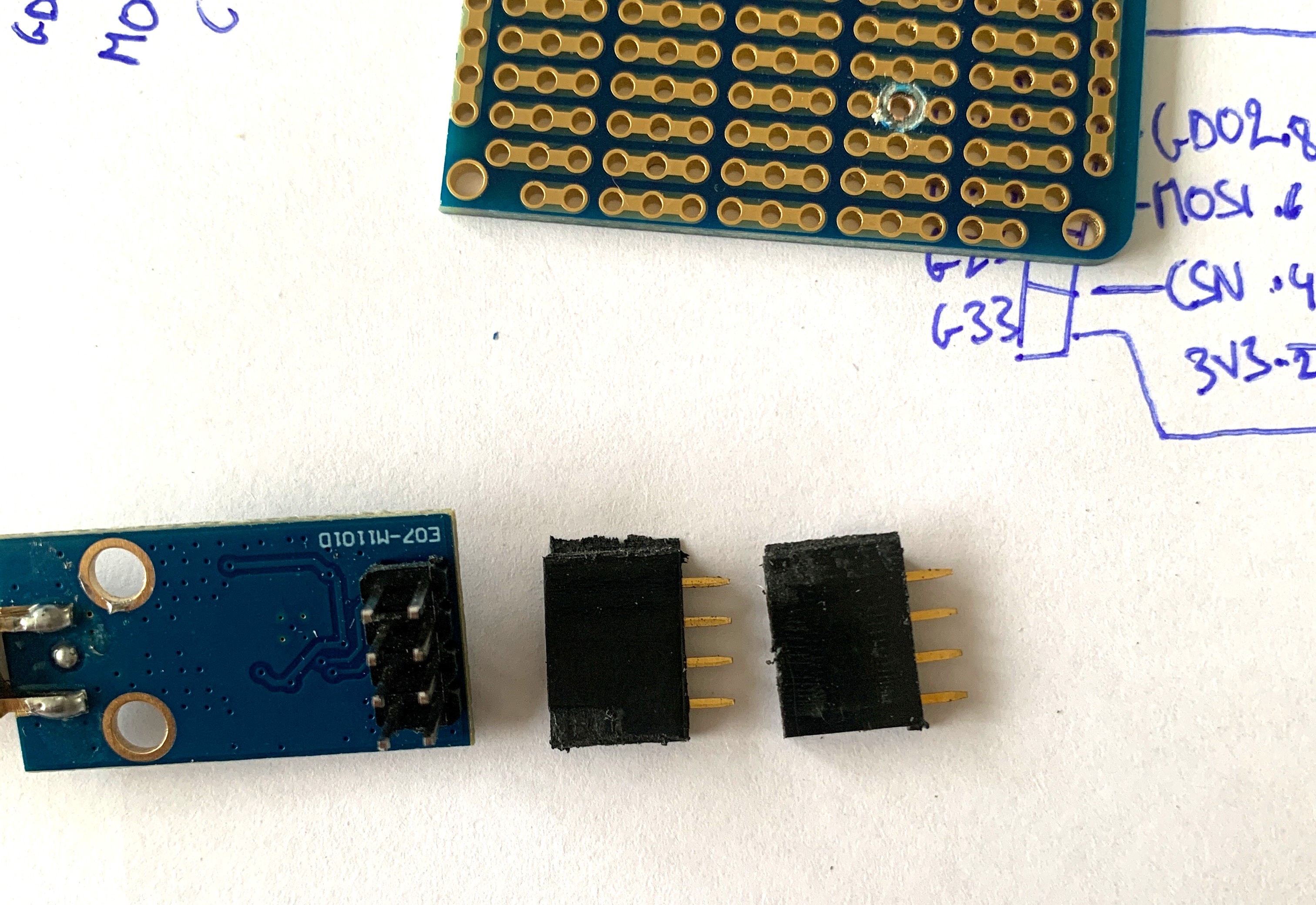
Now that we have all the pieces set, let’s solder!
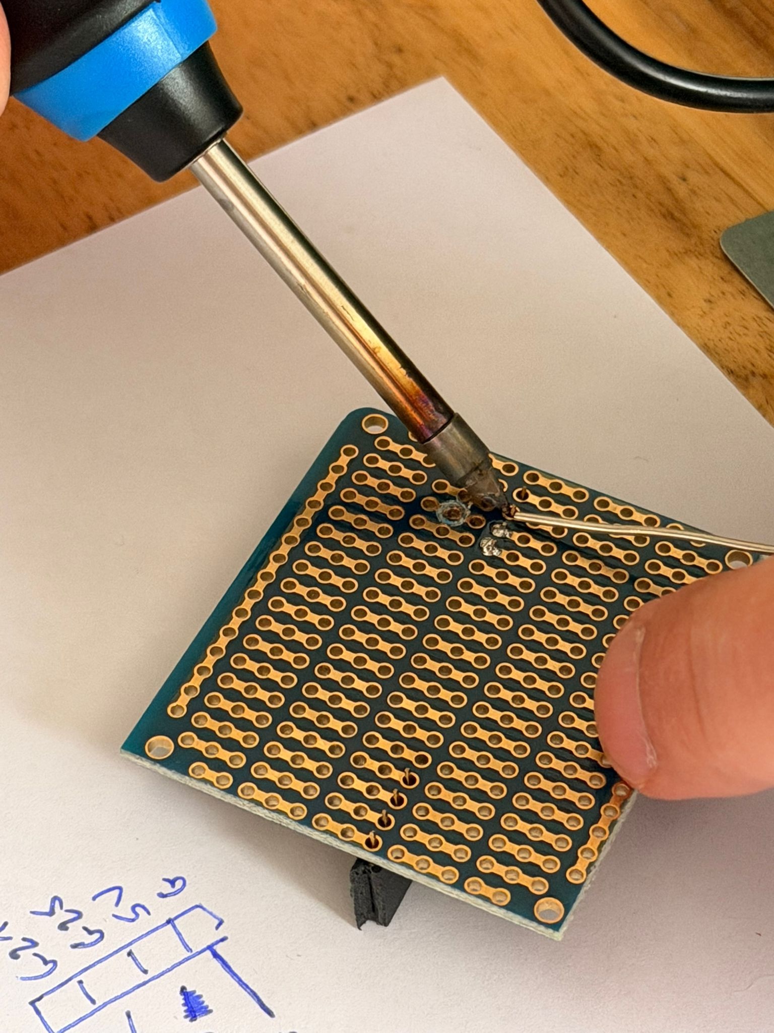
We will need two wires to connect the antenna and the Atom Lite. After decades of stripping wires with a pair of scissors, I invested in a wire stripper and what a quality of life improvement that is!

I did a horrendous job at the soldering so I will only allow you to look it from afar.
I did cut the extra board with a dremel.
The finished product
Next Steps
Now we can plug back the Atom Lite in a USB charger and configure the covers.
I’ll leave you to the official wiki because now you have all that’s needed to follow it.